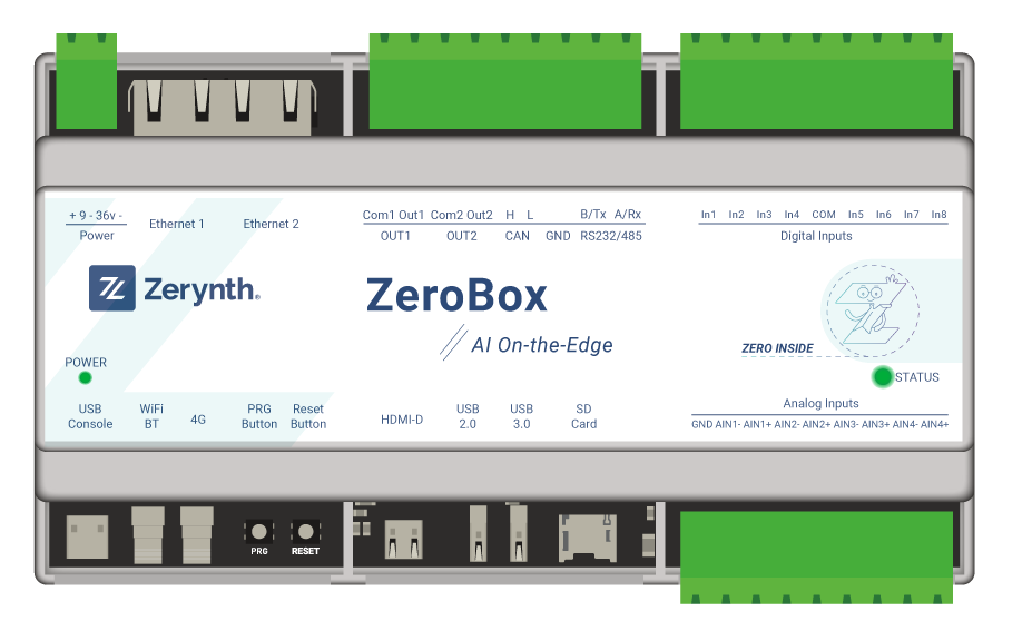
ZeroBox
The ZeroBox is a modular hardware electronic unit with AI on the edge capability that simplifies the development of Industrial IoT applications allowing rapid integration with sensors, actuators, and Cloud services.
Features
- 4 Industrial Analog input channels, 8 Opto-isolated digital channels, 2 solid state photorelay outputs
- Runs on Rockchip RK3586 SoC, 64-bit quad-Core Cortex-A55, 4 x 2.0GHz
- Microchip ATECC608A crypto chip to ensure high-standard security.
- WiFi-and-Bluetooth, Dual Ethernet support.
- Optional Cellular 4G connectivity
- CAN, RS232 and RS485 Interfaces.
- USB 2.0 and 3.0 Interfaces
- DIN-rail mountable (9 slots)
Device Summary
- 4 Industrial Analog input channels, 8 Opto-isolated channels and 2 Solid state photorelay outputs (Max 36Vdc, 150mA).
- Runs on Rockchip RK3586 SoC, 64-bit quad-Core Cortex-A55, 4 x 2.0GHz
- Microchip ATECC608A crypto chip to ensure high-standard security.
- WiFi-and-Bluetooth, Dual Ethernet support.
- Optional Cellular 4G LTE Cat4 with GNSS support.
- CAN, RS232 and RS485, USB 2.0 and 3.0 Interfaces.
- Video HDMI-D port.
- DIN-rail mountable (9 slots).
- 8 to 36V Power Supply.
- MicroSD card slot.
- RGB status led.
- Powered by Zerynth Linux OS – efficient and easy to use, Python enabled OS for IoT applications.
Screw Description
P1 - Power Screw Terminal
| Screw Number | Symbol | Description |
|---|---|---|
| 1 | Power+ | External Power Supply positive pin |
| 2 | Power- | External Power Supply negative pin |
P2 - Photorelay/Communication Screw Terminal
| Screw Number | Symbol | Description |
|---|---|---|
| 1 | COM1 | Common terminal 1 |
| 2 | OUT1 | Normally Opened terminal 1 |
| 3 | COM2 | Common terminal 2 |
| 4 | OUT2 | Normally Opened terminal 2 |
| 5 | CANH | CAN High |
| 6 | CANL | CAN Low |
| 7 | GND | Serial GND |
| 8 | B/TX | RS485 B / RS232 Transmit |
| 9 | A/RX | RS485 A / RS232 Receive |
P3 - Digital Input Screw Terminal
| Screw Number | Symbol | Description |
|---|---|---|
| 1 | IN1 | Digital Input 1 + |
| 2 | IN2 | Digital Input 2 + |
| 3 | IN3 | Digital Input 3 + |
| 4 | IN4 | Digital Input 4 + |
| 5 | GND_COM | Common GND |
| 6 | IN5 | Digital Input 5 + |
| 7 | IN6 | Digital Input 6 + |
| 8 | IN7 | Digital Input 7 + |
| 9 | IN8 | Digital Input 8 + |
P4 - Analog Input Screw Terminal 1
| Screw Number | Symbol | Description |
|---|---|---|
| 1 | AGND | Isolated Ground reference for analog bias |
| 2 | AIN1- | Analog Input 1 - |
| 3 | AIN1+ | Analog Input 1 + |
| 4 | AIN2- | Analog Input 2 - |
| 5 | AIN2+ | Analog Input 2 + |
| 6 | AIN3- | Analog Input 3 - |
| 7 | AIN3+ | Analog Input 3 + |
| 8 | AIN4- | Analog Input 4 - |
| 9 | AIN4+ | Analog Input 4 + |
Switches
Dip-switches
S1 - Handles CAN and Serials Terminals
| Pin | OFF | ON |
|---|---|---|
| 1 | - | 120 ohm R terminator CAN |
| 2 | - | 120 ohm R terminator RS485 |
| 3 | - | Connects RS485 terminal to B/TX terminal |
| 4 | - | Connects RS485 terminal to A/RX terminal |
| 5 | - | Connects RS232 terminal to B/TX terminal |
| 6 | - | Connects RS232 terminal to A/RX terminal |
S2-3 - Handles Analog Outputs
Switch S2-3: each Analog channel can be configured with 3 DIP switches that enable specific features. Each Sx switch controls two Analog channels
S2
| Pin | OFF | ON |
|---|---|---|
| 1 | Gain ADC AIN1 = 1 | Gain ADC AIN1 = 5 |
| 2 | AIN1 read as voltage | AIN1 read as Current |
| 3 | - | AIN1 read as resistive sensor |
| 4 | Gain ADC AIN2 = 1 | Gain ADC AIN2 = 5 |
| 5 | AIN2 read as voltage | AIN2 read as Current |
| 6 | - | AIN2 read as resistive sensor |
S3
| Pin | OFF | ON |
|---|---|---|
| 1 | Gain ADC AIN3 = 1 | Gain ADC AIN3 = 5 |
| 2 | AIN3 read as voltage | AIN3 read as Current |
| 3 | - | AIN3 read as resistive sensor |
| 4 | Gain ADC AIN4 = 1 | Gain ADC AIN4 = 5 |
| 5 | AIN4 read as voltage | AIN4 read as Current |
| 6 | - | AIN4 read as resistive sensor |