Essential
Target Asset
- Retrofitting of auxiliary machinery or production machinery, where interfacing with PLC or inverter is not required (digital protocol interfacing not supported).
- Suitable for simple retrofitting where few signals are required. With this kit, electrical panels are interfaced via 1 power clamp and up to 3 extra signals (machine state, piece counter, scrap counter).
- Retrofitting mac*hines whose status can be inferred via power consumption level analysis (thresholds) or via a dedicated digital signal. When possible, using a power clamp and defining thresholds is preferred, but can be unreliable on some machines.
- This kit is also suitable for minor customization, like reading temperature, humidity or other general purpose analog sensors, but keep in mind that there are only 2 AIN and 2 DIO available on the 4ZeroBox Lite.
Features
- Edge device with 2 DIO for signals reading and 2 AIN for analog sensors.
- 2 AIN can be used for power clamps, other analog signals or also for digital signal sampling (required for scrapes signal detection when available)
- Ethernet/Wifi Connectivity
- The kit includes:
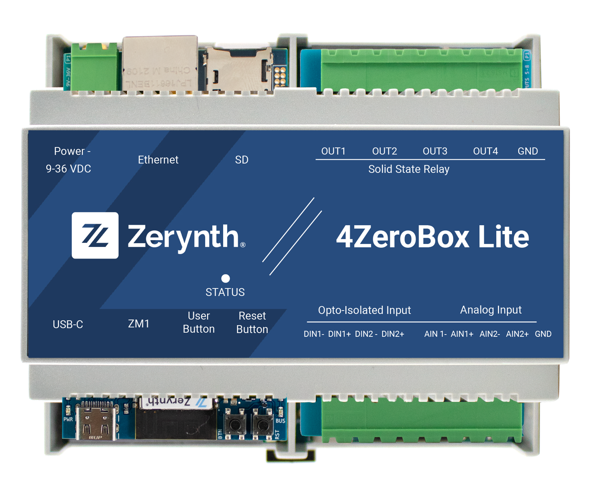
- 1x 4ZeroBox Lite (DB+IO)
- 1x 220-24V power supply,
- 2x decoupling relays,
- 1x 100A power clamp (500A power clamp are also available as addon, verify and notify this need to the delivery team)
General Hardware Characteristics
DB-ZM1
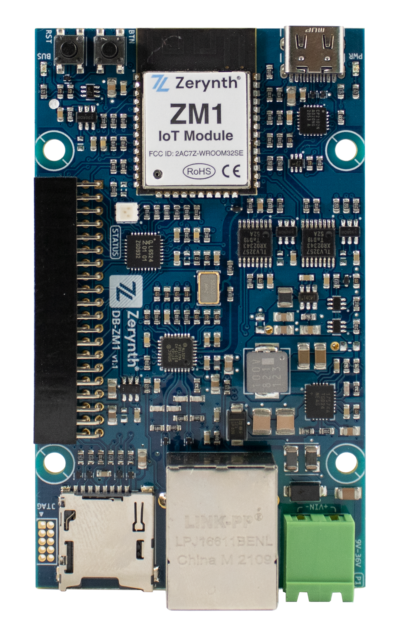
The ZM1-DB is a flexible, modular, board that features the ZM1 SoM
- ZM1 Module
- 32-bit dual Core MCU based on ESP32-WROOM-32SE;
- Clock frequency up to 240 MHz;
- Embedded 16 MB SPI Flash Memory;
- Integrated ATECC608A crypto element allowing ultra-secure communications;
- WiFi Support;
- 9 to 36V input Power Supply;
- MicroSD card slot;
- Ethernet Support;
- Reset and User Buttons;
- RGB status LED;
- USB-C power and programming.
EXP-IO
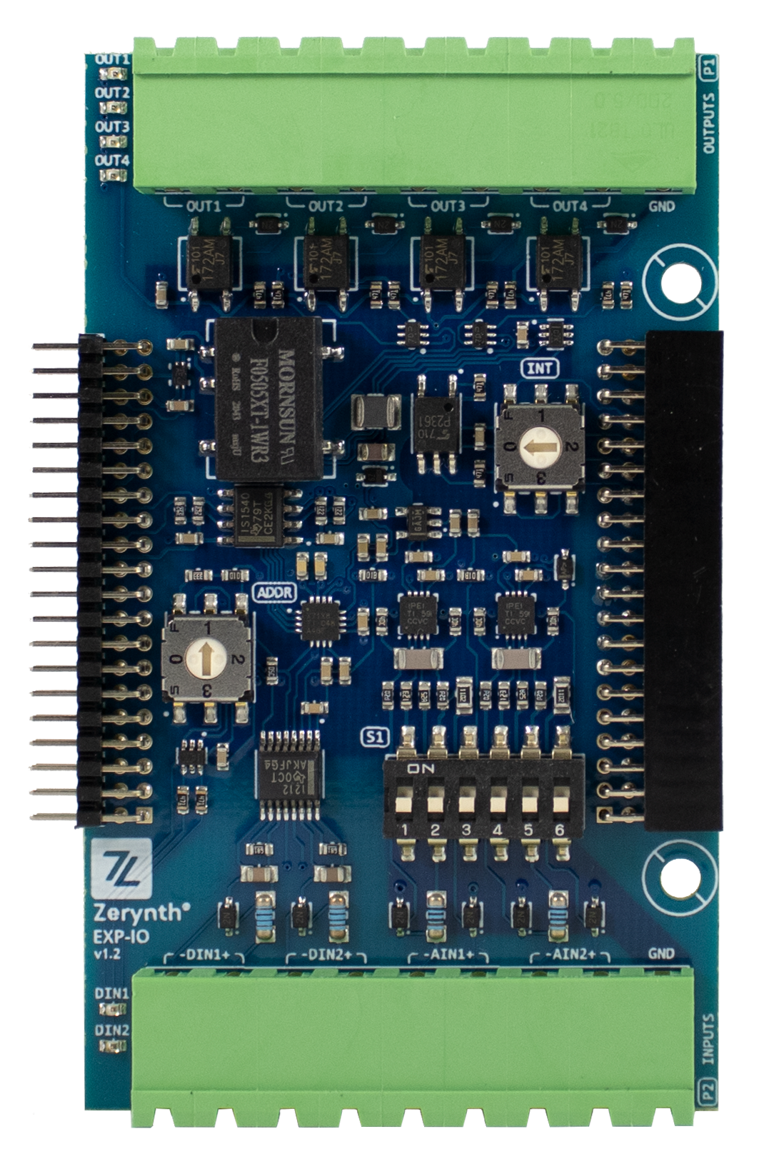
The EXP-IO expansion board is a mixed input/output module that features:
- 2 Opto-Isolated Digital Inputs
- Von = 10.1 VDC (typ);
- Voff = 9.0 VDC (typ);
- Vmax = 36 VDC;
- Imax = 1.86 mA (typ);
- compatible with IEC 61131-2 Type 3;
- 2 Analog Channels configurable as
- 4-20 mA Current channel (full input range ̣±20 mA);
- 0-10V Voltage Channel (full input range ±10 V);
- Resistive Sensor Channel, which can be used for digital signal sampling;
- 4 Solid State Relays NO
- Vmax (open circuit) = 36 VDC;
- Imax (closed circuit) = 150 mA;
Screw Description
DB-ZM1
Connector J1
| Screw Number | Symbol | Description |
|---|---|---|
| 1 | Power+ | External Power Supply positive pin |
| 2 | Power- | External Power Supply negative pin |
EXP-IO
P1 - Upper Screw Terminal
| Screw Number | Symbol | Description |
|---|---|---|
| 1,2 | OUT1 | Screw Terminal of the relay #1 ( OUT1 is normally open) |
| 3,4 | OUT2 | Screw Terminal of the relay #2 ( OUT2 is normally open) |
| 5,6 | OUT3 | Screw Terminal of the relay #3 ( OUT3 is normally open) |
| 7,8 | OUT4 | Screw Terminal of the relay #4 ( OUT4 is normally open) |
| 9 | GND | Isolated Ground reference for analog bias |
P2 - Lower Screw Terminal
| Screw Number | Symbol | Description |
|---|---|---|
| 10 | DIN1- | Digitally opto-Isolated digital Inputs |
| 11 | DIN1+ | Digitally opto-Isolated digital Inputs |
| 12 | DIN2- | Digitally opto-Isolated digital Inputs |
| 13 | DIN2+ | Digitally opto-Isolated digital Inputs |
| 14,15 | AIN1-/AIN1+ | Analog Input Channel 4-20mA/0-10V/Resis./Current |
| 16,17 | AIN2-/AIN2+ | Analog Input Channel 4-20mA/0-10V/Resis./Current |
| 18 | GND | Isolated Ground reference for analog bias |
NOTE: All I/O pins on screw terminals are isolated from the zBUS interface.
- Isolation: 125V(rms) / 1500V(peak)
- Overvoltage Cat.II / Pollution Deg.II
NOTE: Analog channel to channel isolation > 250kΩ
Switches
Rotary-switches
ADDR SW: Chooses the address of the ADC Chip. Enable multiple boards to be connected simultaneously. Present in EXP-IO as SW1.
| Position | Address |
|---|---|
| 0 | 0x10 |
| 1 | 0x11 |
| 2 | 0x12 |
| 3 | 0x13 |
INT SW: Controls which hardware channel you want to link the interrupt. Present in EXP-IO as SW2.
| Pin | Pin on zBUS | Pin ZM1-DB |
|---|---|---|
| 0 | INTR | D35 |
| 1 | INTB | NC |
| 2 | INTE1 | D46 |
| 3 | INTE2 | D47 |
Dip-switches
EXP-IO has a different set of dip-switches that allow it to change the configuration of the expansion.
Switch S1: each Analog channel can be configured with 3 DIP switches that enable specific features.
| Pin | OFF | ON |
|---|---|---|
| 1 | Gain ADC AIN1 = 1 | Gain ADC AIN1 = 5 |
| 2 | AIN1 read as voltage | AIN1 read as Current |
| 3 | - | AIN1 read as resistive sensor |
| 4 | Gain ADC AIN2 = 1 | Gain ADC AIN2 = 5 |
| 5 | AIN2 read as voltage | AIN2 read as Current |
| 6 | - | AIN2 read as resistive sensor |
Technical Specifications
| Power Supply | |
| Voltage | 9-36 V DC |
| Power Consumption | Typical: 1 W; Maximum: 5 W. |
| Inputs / Outputs | |
| Microcontroller I/O Pin Voltage | Max supported voltage: 3.3 V |
| Environmental Conditions | |
| Temperature | -40 to +85 °C |
| Humidity | Max 80% (not condensing) |
| Storage Temperature | -40 to +85 °C |
| Degree Protection | < IP40 |
| Connectors | |
| Ethernet | RJ45 Connector |
| Programming | USB-C Connector |
| Micro SD | Micro SD Slot |
| Operating Frequency | ||
| Categories | Items | Specifications |
| Certification | RF Certification | FCC/CE-RED |
Green Certification | RoHS/REACH | |
| Test | Reliability | HTOL/HTSL/uHAST/TCT/ESD |
| Wi-Fi | Protocols | 802.11 b/g/n (802.11n up to 150 Mbps) |
A-MPDU and A-MSDU aggregation and 0.4 µs guard interval support | ||
Frequency Range | 2.4 ~ 2.5 GHz | |
| Bluetooth | Protocols | Bluetooth v4.2 BR/EDR |
Radio | NZIF receiver with –97 dBm sensitivity | |
NZIF receiver with –97 dBm sensitivity | ||
AFH | ||