Signal acquisition
To enable the Retrofitting, two types of signals might be acquired from the machine.
Digital Signal Acquisition
Basics
Digital signals are Voltage signals that rappresent a logic value. They are rappresented with value 1 for logic value true and 0 for the logic value false.
Usually they are used as pices counters or alerts/machine status.
Hardware Acquisition
Digital signals can be acquired connecting the logic line of the machine to one of the Digital Input of the Zerynth Device (usually on the 0-36V range). A free contact relay can be placed between the logic line and the Digital Input to avoid overtension on the device.
Software Acquisition
Digital signals acquisition can be enabled by the configurator both using the wizard and the graph editor.
-
Wizard: most of the applications supported by the wizard allow the user to configure digital signal acquisition.
- Digital signals as counters: in the following image a Digital Input is configured to acquire a logic signal that rappresents the number of pices produced.
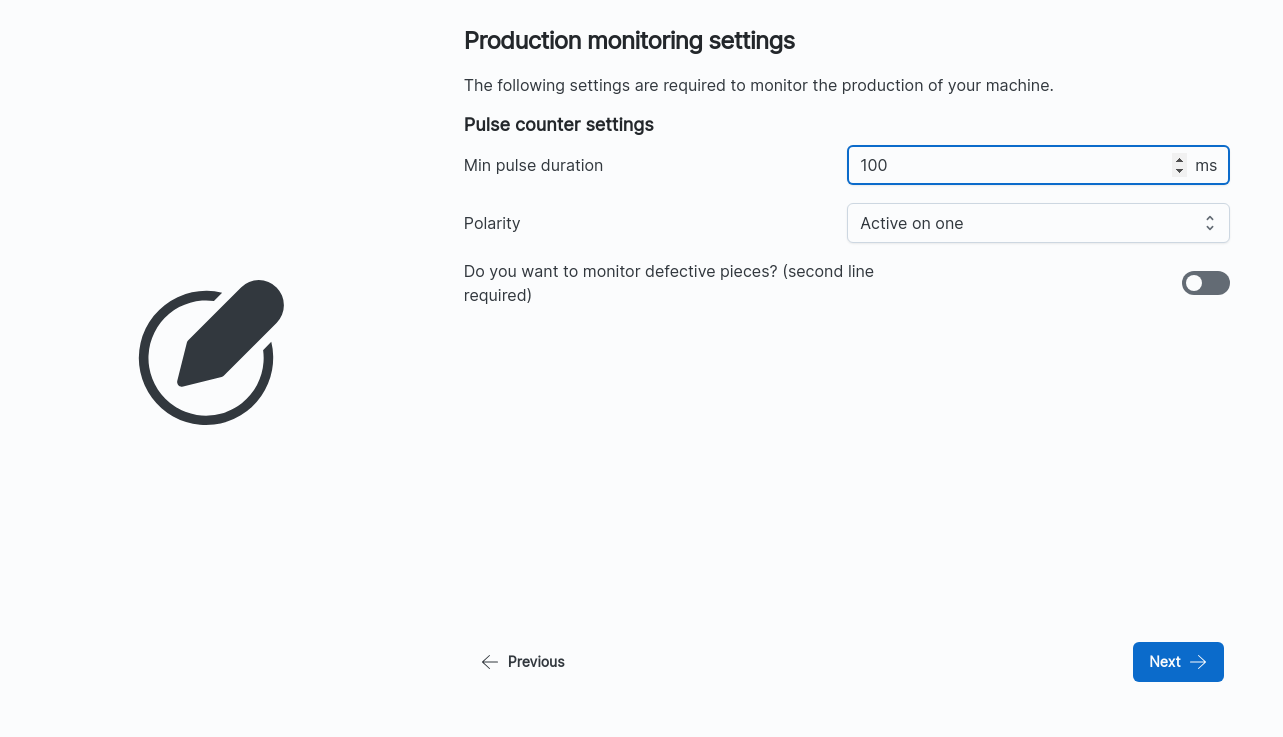
The pieces counter in the above image is configured to use a logic pulse to count produced good pieces. The pusle must be at least 100 ms long to increase the counter (
minimum pulse duration) with the active value configured to logictrue(Polarity). An additional counter line can be activated to count bad pieces with the toggle button.- Digital signal as alarm: in the following image a Digital Input is configured to acquire a machine's alarm.
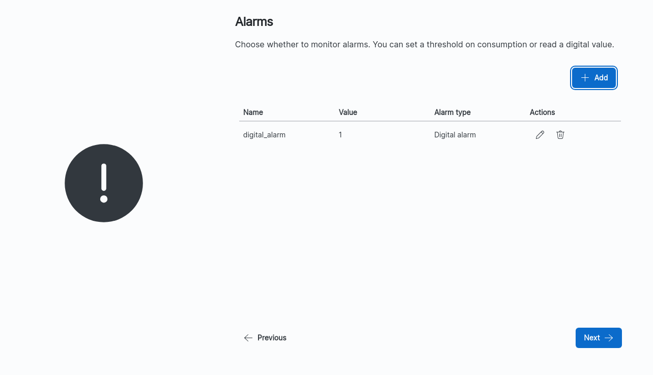
The alarm in the above image is configured to trigger when the logic value of the line is
true. This will also generate an alarm event that will be sent to the cloud interface. Configurable settings arenameof the alarm and triggervalue. -
Graph Editor: digital inputs are suppoted by the graph editor throught the
Level Sensornode.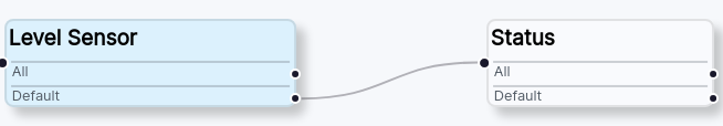
In the above image, a Digital Signal is acquired using a
Level Sensornode. This node acquire the signal interfacing directly to the hardware and generates an output with the acquired value, which can be used as input by other nodes. In this case a status node is using theLevel Sensoroutput as input to decide the machine status.
Analog Signal Acquisition
Basics
Analog signals are Voltage or Current signals that are used to rappresent a physical property of the machine. Analog Signals are discrete and are acquired throught Analog to Digital Converters (ADCs). Thay are usually used in retrofitting to acquire che power consumptions of the machine with the use of a Current Clamp. The
Hardware Acquisition
Analog signals can be acquire connecting the signal line of the machine or of the analog sensor used (Clamps, etc...) to one of the Zerynth Device, which support Voltage (0-10V), Current (4-20mA) or resistive measurements.
Software acquisition
Analog signals acquisition can be enabled by the configurator using both the wizard and the graph editor.
-
Wizard: most of the application supported by the wizard allow the user to configure analog signal acquisition thought a Current Clamp sensor.
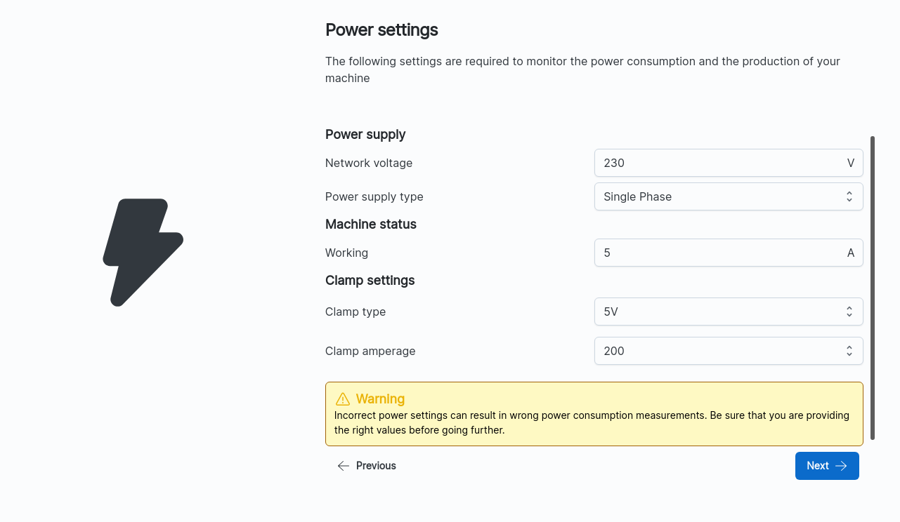
In the above image, the wizard is used to configure an Analog signal acquisition throught an
0-5 V/200 ACurrent Clamp sensor. The analog acquisition is configured to read the consumptions of machine connected to a230 Vline with a single phasepower supply. TheMachine Statuswill be consideredworkingwhen the consumption will be above5 A.
As shown in the above image, Analog Signals can be used to generate alarms when a certain threshold in
Wis surpassed (1000 W in the example). Configurable settings arenameof the alarm and triggervalueinW. -
Graph Editor: Analog Signals are supported by the graph editor throught a multitude of Nodes, more precisely by the generic
AnalogSensornode and by the specificPowerSensor,VoltageSensor,CurrentSensor, andResistiveSensornodes.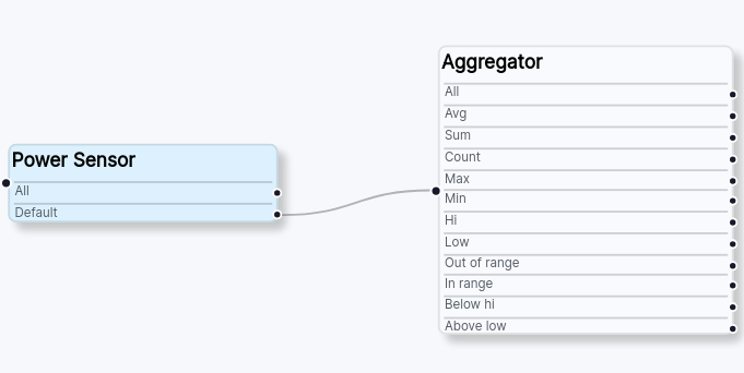
In the above image, an Analog Signal is acquired using a
PowerSensornode. This node acquire the signal interfacing directly to the hardware and generates an output with the acquired value, which can be used as input by other nodes. In this case by anAggregatorthat will aggregate the acquire data in different outputs.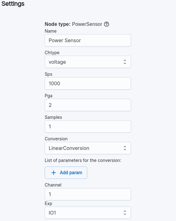
All the analog sensors node, can be configured to adapt to the user specific case. The above picture shows the settings of the example. Since we are using a 0-5 V clamp the
Chtypeis set tovoltage, with1000 sps,1 pgaand1 Sampleper measurement. The conversion isLinearConversion. The signal is acquired throught theChannel 1of theEXP-IO1of the kit.